2-Channel Temperature Monitor with Dual,
Automatic, PWM Fan-Speed Controller
2
Maxim Integrated
MAX6639/MAX6639F
ABSOLUTE MAXIMUM RATINGS
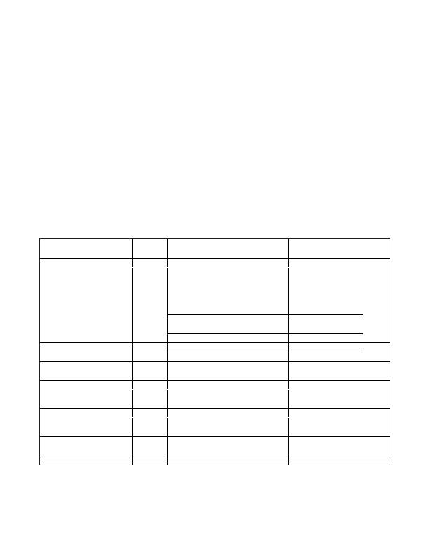
ELECTRICAL CHARACTERISTICS
(V
CC
= +3.0V to +3.6V, T
A
= 0癈 to +125癈, unless otherwise noted. Typical values are at V
CC
= +3.3V, T
A
= +85癈.) (Note 1)
Stresses beyond those listed under
Absolute Maximum Ratings
may cause permanent damage to the device. These are stress ratings only, and functional
operation of the device at these or any other conditions beyond those indicated in the operational sections of the specifications is not implied. Exposure to
absolute maximum rating conditions for extended periods may affect device reliability.
V
CC
to GND..............................................................-0.3V to +4V
PWM1, PWM2, TACH1, and TACH2 to GND ......-0.3V to +13.5V
DXP1 and DXP2 to GND..........................-0.3V to +(V
CC
+ 0.3V)
DXN to GND ..........................................................-0.3V to +0.8V
SCL, SDA, THERM, OT, FANFAIL, ADD,
and ALERT to GND ..............................................-0.3V to +6V
SDA, OT, THERM, ALERT, FANFAIL,
PWM1, and PWM2 Current .............................-1mA to +50mA
DXN Current .......................................................................?mA
ESD Protection (all pins, Human Body Model) ..................2000V
Continuous Power Dissipation (T
A
= +70癈)
16-Pin QSOP (derated 8.3mW/癈 above +70癈) ....... 667mW
16-Pin TQFN 5mm x 5mm
(derated at 33.3mW/癈 above +70癈)................2666.7mW
Operating Temperature Range .........................-40癈 to +125癈
Junction Temperature......................................................+150癈
Storage Temperature Range ............................-65癈 to +150癈
Lead Temperature (soldering, 10s).................................+300癈
Soldering Temperature (reflow).......................................+260癈
PARAMETER
SYMBOL
CONDITIONS
MIN
TYP
MAX
UNITS
Operating Supply Voltage Range
V
CC
+3.0
+3.6
V
Standby Current
SMB static, sleep mode
3
10
礎
Operating Current
Interface inactive, ADC active
0.5
1
mA
V
CC
= +3.3V, +60癈 d T
A
d +100癈 and
+60癈 d T
R
d +100癈
-1.0
+1.0
V
CC
= +3.3V, +40癈 d T
A
d +100癈 and
0癈 d T
R
d +145癈
-2.5
+2.5
External Temperature Error
MAX6639AEE, MAX6639ATE:
n = 1.008
MAX6639FAEE: n = 1.021
V
CC
= +3.3V, 0癈 d T
R
d +145癈
-3.8
+3.8
癈
V
CC
= +3.3V, +25癈 d T
A
d +100癈
-2.0
+2.0
Internal Temperature Error
MAX6639AEE, MAX6639ATE
V
CC
= +3.3V, 0癈 d T
A
d +125癈
-4.0
+4.0
癈
V
CC
= +3.3V, +25癈 d T
A
d +100癈
-7.7
-2.5
Internal Temperature Error
MAX6639FAEE
V
CC
= +3.3V, 0癈 d T
A
d +125癈
-10.4
-0.1
癈
Supply Sensitivity of Temperature
Measurement
?.2
癈/V
+0.125
癈
Temperature Resolution
11
Bits
Conversion Time
125
ms
Conversion-Rate Timing Error
-10
+10
%
PWM Frequency Error
-10
+10
%
Tachometer Accuracy
T
A
= +60癈 to +100癈
?
%
High level
70
100
130
Remote-Diode Sourcing Current
Low level
7.0
10
13.0
礎
DXN Source Voltage
0.7
V
发布紧急采购,3分钟左右您将得到回复。
相关PDF资料
MAX6641AUB92+
IC TEMP MONITOR SMBUS 10UMAX
MAX6642ATT94+T
IC TEMP SENSOR SMBUS 6TDFN
MAX6643LBFAEE+
IC CTLR PWM FAN-SPEED 16QSOP
MAX6649MUA/V+
IC SENSOR REMOTE SMBUS 8UMAX
MAX6652AUB+T
IC TEMP SENS/MON 10-UMAX
MAX6659MEE+T
IC TEMP SENSOR SMBUS 16-QSOP
MAX6661AEE+T
IC REG FAN SPEED 16-QSOP
MAX6664AEE+T
IC TEMP MON FAN CNTRL 16-QSOP
相关代理商/技术参数
MAX6639FATE+T
功能描述:板上安装温度传感器 2Ch Temperature Monitor RoHS:否 制造商:Omron Electronics 输出类型:Digital 配置: 准确性:+/- 1.5 C, +/- 3 C 温度阈值: 数字输出 - 总线接口:2-Wire, I2C, SMBus 电源电压-最大:5.5 V 电源电压-最小:4.5 V 最大工作温度:+ 50 C 最小工作温度:0 C 关闭: 安装风格: 封装 / 箱体: 设备功能:Temperature and Humidity Sensor
MAX6639YAEE+
功能描述:板上安装温度传感器 2Ch Temperature Monitor RoHS:否 制造商:Omron Electronics 输出类型:Digital 配置: 准确性:+/- 1.5 C, +/- 3 C 温度阈值: 数字输出 - 总线接口:2-Wire, I2C, SMBus 电源电压-最大:5.5 V 电源电压-最小:4.5 V 最大工作温度:+ 50 C 最小工作温度:0 C 关闭: 安装风格: 封装 / 箱体: 设备功能:Temperature and Humidity Sensor
MAX6639YAEE+T
功能描述:板上安装温度传感器 2Ch Temperature Monitor RoHS:否 制造商:Omron Electronics 输出类型:Digital 配置: 准确性:+/- 1.5 C, +/- 3 C 温度阈值: 数字输出 - 总线接口:2-Wire, I2C, SMBus 电源电压-最大:5.5 V 电源电压-最小:4.5 V 最大工作温度:+ 50 C 最小工作温度:0 C 关闭: 安装风格: 封装 / 箱体: 设备功能:Temperature and Humidity Sensor
MAX663C/D
功能描述:低压差稳压器 - LDO RoHS:否 制造商:Texas Instruments 最大输入电压:36 V 输出电压:1.4 V to 20.5 V 回动电压(最大值):307 mV 输出电流:1 A 负载调节:0.3 % 输出端数量: 输出类型:Fixed 最大工作温度:+ 125 C 安装风格:SMD/SMT 封装 / 箱体:VQFN-20
MAX663CJA
功能描述:低压差稳压器 - LDO RoHS:否 制造商:Texas Instruments 最大输入电压:36 V 输出电压:1.4 V to 20.5 V 回动电压(最大值):307 mV 输出电流:1 A 负载调节:0.3 % 输出端数量: 输出类型:Fixed 最大工作温度:+ 125 C 安装风格:SMD/SMT 封装 / 箱体:VQFN-20
MAX663CPA
功能描述:低压差稳压器 - LDO 5V Prog uPower Voltage Regulator RoHS:否 制造商:Texas Instruments 最大输入电压:36 V 输出电压:1.4 V to 20.5 V 回动电压(最大值):307 mV 输出电流:1 A 负载调节:0.3 % 输出端数量: 输出类型:Fixed 最大工作温度:+ 125 C 安装风格:SMD/SMT 封装 / 箱体:VQFN-20
MAX663CPA+
功能描述:低压差稳压器 - LDO 5V Prog uPower Voltage Regulator RoHS:否 制造商:Texas Instruments 最大输入电压:36 V 输出电压:1.4 V to 20.5 V 回动电压(最大值):307 mV 输出电流:1 A 负载调节:0.3 % 输出端数量: 输出类型:Fixed 最大工作温度:+ 125 C 安装风格:SMD/SMT 封装 / 箱体:VQFN-20
MAX663CSA
功能描述:低压差稳压器 - LDO 5V Prog uPower Voltage Regulator RoHS:否 制造商:Texas Instruments 最大输入电压:36 V 输出电压:1.4 V to 20.5 V 回动电压(最大值):307 mV 输出电流:1 A 负载调节:0.3 % 输出端数量: 输出类型:Fixed 最大工作温度:+ 125 C 安装风格:SMD/SMT 封装 / 箱体:VQFN-20
